- Hood Depot International, Inc., 710 S. Powerline Rd Suite H • Deerfield Beach, FL 33442|
- 954-570-4083|
- 954-570-9865
Toll Free: 1-800-322-8730


Furnish Hood Depot’s ventilator model SW(PF) (ventilator without fire damper at the inlet slot) as shown on plans, with a depth of and an overall length of and to meet the following requirements:
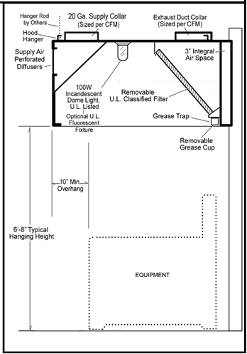
GENERAL DESCRIPTION: Ventilator is a conventional filter-type hood with continuous array of baffle U.L. Classified filters along the entire ventilator length. Ventilators up to 12’ to include semi-concealed pitched gutter which slopes to removable grease cup. Ventilators over 12’ include two pitched gutters that slope to removable grease cups located at each extreme end. Ventilator shall include means for hanging.
CONSTRUCTION MATERIALS: The ventila-tor shall be 18 gauge all-stainless steel con- struction. A number 4 finish shall be provided on all exposed surfaces.
LIGHT FIXTURES: Ventilator shall be equipped with U.L. Listed 100 Watt Dome Incandescent or Recessed 150 Watt In- candescent or Recessed Fluorescent fixtures. Light fixtures shall be prewired to a single point of connection at the factory.
APPROVALS: Ventilator to be U.L. Listed, list- ed by NSF, and in accordance with all recom- mendations of NFPA 96. The ventilator must meet all applicable codes.
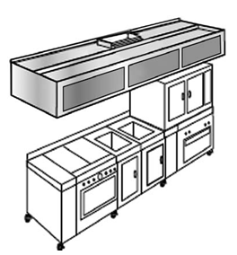
Wall mounted canopy style ventilator for use over medium duty equipment suitable for interior ceiling heights less than 8’6” by recessing into false ceiling.
These SW(PF) Series models are low velocity wall-mounted canopy ventilators with front perforated supply air, which are U.L. Listed under the category of “Exhaust Hood Without Exhaust Damper.” Units are available in custom depths depending on particular cooking battery layout. Models include a full array of U.L. classified grease removing filters and a grease collecting gutter sloped to a removeable grease cup at either end. Supply air is to be introduced through perforated diffusers on the face of the hood.
When properly operated and maintained, the liquefied grease is drained off into a con- tainer for periodic removal and cleaning.
At periodic intervals (such as the end of each cooking day) the filters are to be re- moved and cleaned. They may be washed in a dishwasher, hand washed or soaked and rinsed.
Appropriately conditioned supply air must be mechanically delivered to the space to re- place exhausted air. Generally 50-80% is so delivered through the hood with the remain- ing 20-50% flowing naturally from adjoining areas and through the HVAC system.
Exhaust fan(s) and supply fan(s) are available. See fan section of catalog or web site for design information. Fans must be designed for Hood Depot air volumes and static pres- sure drop for the entire system and must be in compliance with local codes.
NFPA96 and most other codes require a fire extinguishing system for protection of both the duct collar and plenum areas of ventilators and for the protection of cooking equip- ment such as fat fryers, griddles, ranges and broilers which may be source of ignition of grease. Check with local fire authorities for exact requirements.
Consult Hood Depot regarding custom services addressing:
EQUIPMENT TYPE: MEDIUM LOAD..........Kettles (under 60 Gals.), hot top ranges, gas fryers, griddles HEAVY LOAD.............Charbroilers, high grease equipment
An optional Hood Depot Control Panel can be provided for each exhaust fan. A contactor or motor starter will be provided for each fan. See section “Control Panels” in our catalog or visit our web site for more information.
Static pressure drops across ventilator: Model SW(PF).......................0.625 W.G. at the duct collar
Hood Depth 48” 54” 60” 66” (Other depths avail.) Wgt. per lin. ft. (LBS) 60 70 75 80
Light & Medium duty: Cooking surfaces to 400˚= 250 cfm / lf. of exhaust air and 200 cfm / If of supply air Heavy duty: Cooking sur- faces to 850˚= 280 cfm / lf of exhaust air and 224 cfm / If of supply air. CFM criteria can vary and a higher cfm/lf is sometimes factory advised; contact us for specific appliance airflow recommendations.

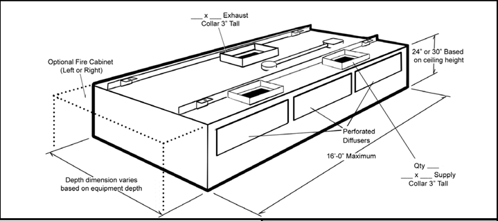
Canopies available in widths of 48”, 54”, 60” and 66”. Height can be 24” or 30” depending on ceiling height. Custom widths and heights available; contact factory.
Hood lengths available from 4’0” to 16’0” in 6” increments. For lengths 6’6” to 12’0” the maximum offset from centerline and/or make-up air openings to end of hood shall not exceed 6”0”. Lengths from 12’0” to 16’0” shall incorporate two exhaust ducts, each not to exceed 6’0” on center. Filters and lights are added in proportion to length.


Copyright © 2019 Hooddepot.net
All Rights Reserved
